Software Installation
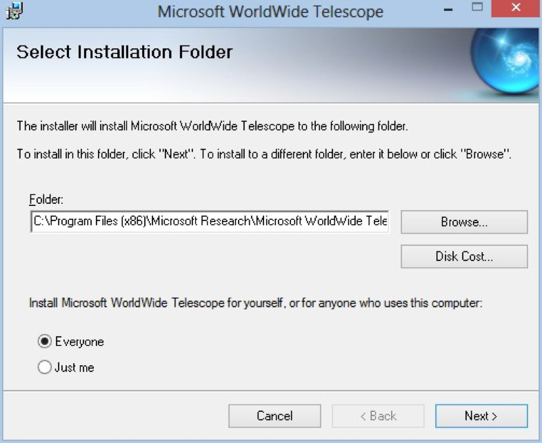
- Install WWT Windows Client on all Servers both Master and Projector servers, http://www.worldwidetelescope.org
-
Install with default folder path
C:\Program Files (x86)\Microsoft Research\Microsoft WorldWide Telescope -
The GUI or Master control channel needs to be a separate server from the projection channels
-
Install Remote Control for Cluster Operation
- Remote can:
- Wake and shutdown projector server
- Shutdown WWT on projector server
- Startup WWT on projector server
- Record IP and MAC address for each node
- Turn off screen saver and energy saver settings for each node
- Both WWT and WWTRemote Control should be running on each slave/node for the projection to work correctly
- Remote can:
-
Install Excel Add-In for WWT
-
Run WWT on each server independently before attempting to setup cluster.
- Run a tour or navigate around to load data into the cache
- WWT needs the cache folder populated to run smoothly
-
Populate cluster configuration files
-
Create a wwtconfig folder in the root directory of each server including Master controller (
C:\wwtconfig) -
Start WWT on each node – master and projection servers
-
After WWT has fully started, exit program. This will cause a
config.xmlfile to be created in the folderC:\wwtconfig -
Using a text or XML editor, change the
config.xmlfile as follows for each of the projector nodes
Example config.xml for projector nodes.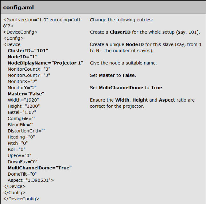
- Create a unique cluster ID
- Create a node ID
- Change node Display name (such as dome orientation – where it is aimed)
- Set Master to False
- Enter actual resolution for your display in Width, and Height
- Set MultiChannelDome to True
- Save file and close editor
-
Using a text or XML editor, change the config.xml file as follows for the Master node Example config.xml for Master node.
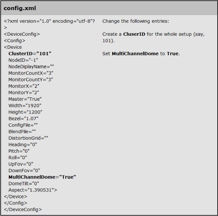
- Enter your unique cluster id
- Change Node Id to -1
- Check and ensure Master is set to True
- Enter actual resolution for your display in Width, and Height
- Set MultiChannelDome to True
- Save file and close editor
-
-
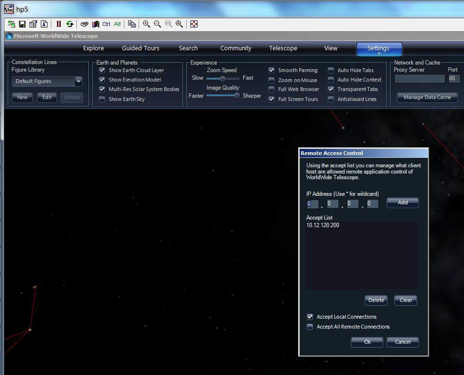
Open Remote Access Control under Settings>Remote Access Control on each node Select Remote Access Control.
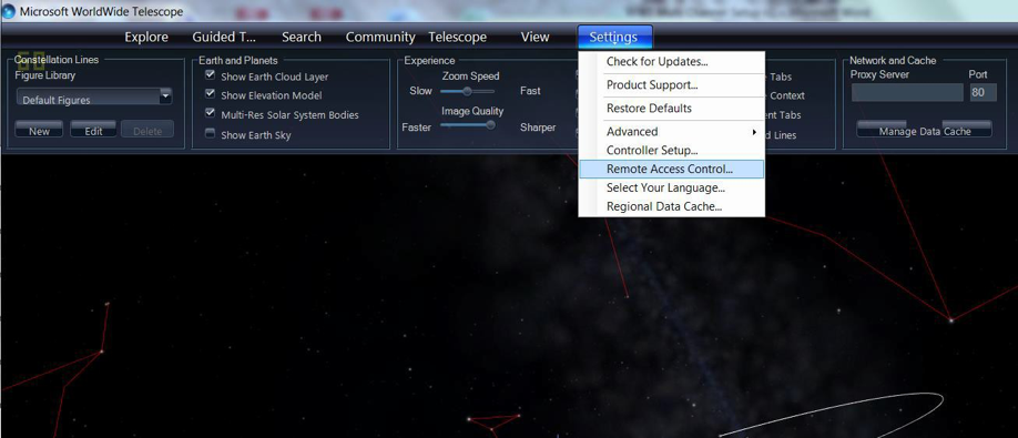
- Enter the IP address of your Master Controller Node. This ensures only you will have control of your nodes at all times.
- Check Accept Local Connections.
Setting IP address for Remote Access Control.
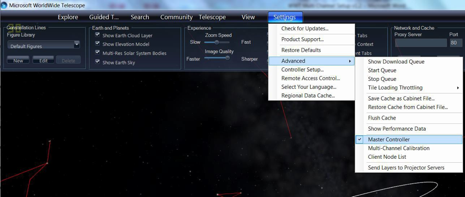
- Launch WWT on Master Controller node
- On Master Controller Node Ensure under
Settings>Advancedthat Master Controller is checked
Setting a node as Master Controller.
- Open Projector Server List under
Settings> Advancedto ensure you can see all nodes, and they are green. This pane will also tell you frame rates and other useful information for each node.
Opening Projector Server List.

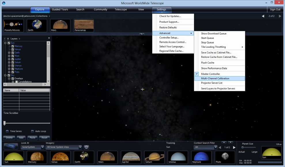
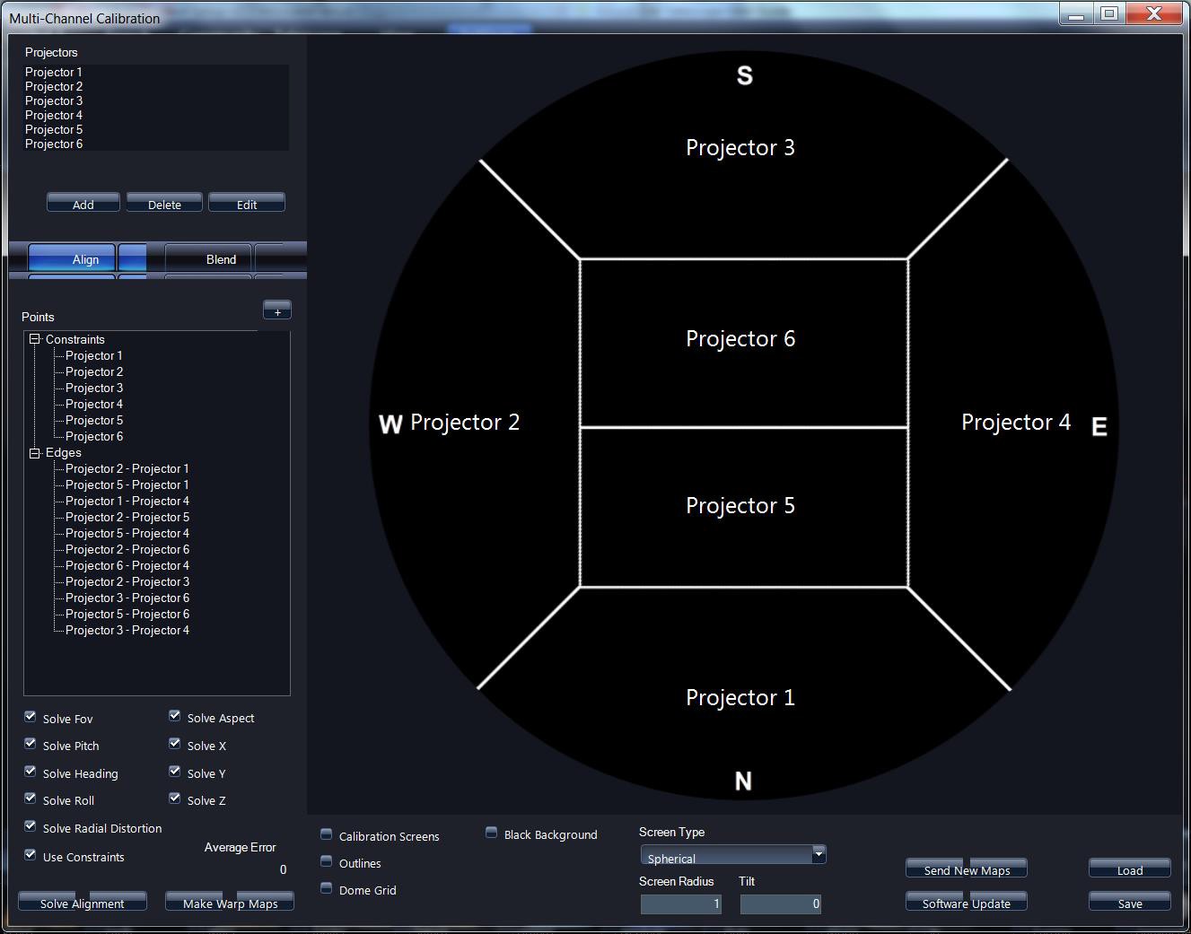
- Open
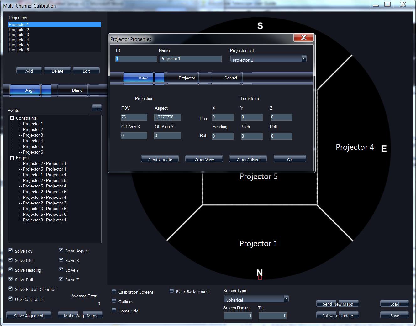
Settings>Advanced>Multi Channel Calibration
Selecting Multi-channel calibration.
-
Set specifics for the projection area
- Select the type of screen as Spherical
- Set Screen Radius in meters
- Set Tilt to locate center of interest in the display. (example: A value
of 60 indicates that main focus of most viewers will be on a point 60
degrees up from the spring-line)
-
Set number of projectors in the top left panel
- Left click to highlight a channel
- The layout example is fixed and will not change from a six channel example
- Five channels is considered the minimum for a dome setup
- As you update your Projector names the text on the dome map will update
-
Change properties for each channel by left clicking the channel you wish to edit and click the edit button
- Set each channel with the unique id, and name that was set earlier in the XML file
- View tab contains the idealized settings for the projector if it was centered exactly in the middle of the dome
- Projector tab pertains to the actual physical location of the projector
- Solved tab contains the temporary output from a Solve Alignment calculation