Projector Values
Specifying projector values.
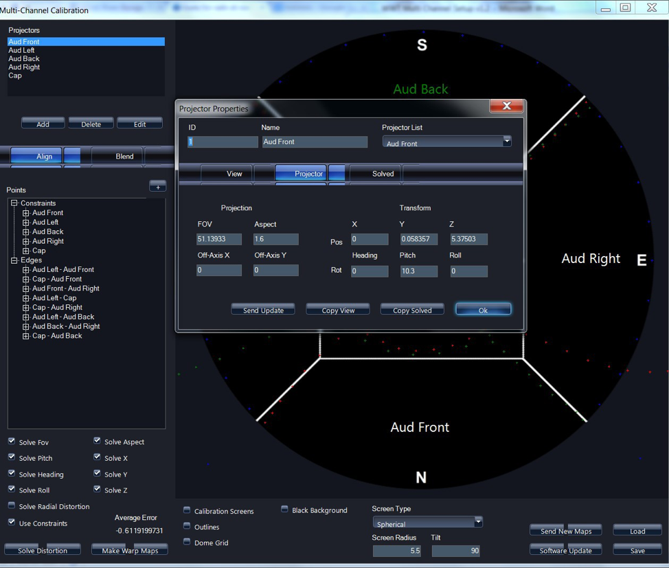
- Enter Projector Values for each projector. This is where the projector is physically located in the dome.
- Enter FOV and Aspect Values
- Values for
Pos- X,Y,Zare in meters
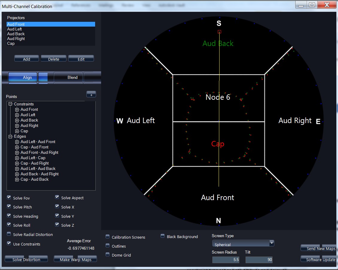
- When you are finished entering in values for each projector, verify the orientation in the simulation pane for each projector and that it is correct
- The red box indicates relative projector location
- The yellow line represents the projection cone
In this example, my Audience front projection area is being projected from
the rear of the dome, onto the front of the dome.
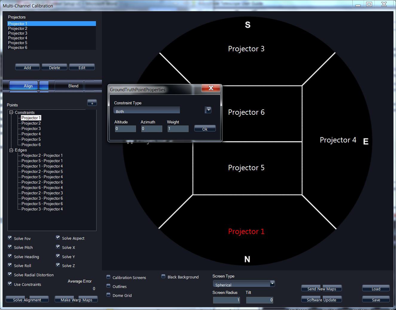
- Set constraints (Spring-line, Zenith) by left clicking on the projection channel under points, and then right clicking to bring up properties.
- Physical constraints on the dome that anchor the alignment (Zenith, spring line)
- These points need to be placed as close as possible to each 10 degree physical mark on the dome.
- While you are physically inside the dome, add a point and use left click to drag the point or “x” onto the corresponding 10 degree point in your dome.
- Enter actual values for Altitude and Azimuth
- Most constraints will only have altitude selected from the drop down constraint type with a value of 0 for 180 degree domes. For domes with a 160 degree radius you must enter the value for altitude as 10. North (AZ=0), South (AZ=180), East (AZ=90), and West (AZ=270) that will have a constraint type set as both Altitude and Azimuth.
- The Cap Center Point or Zenith will have a constraint type set as Both in the dropdown menu with values of Alt=90, AZ=0, Weight of 10.
- Weight refers to that points gravity, most points should be left at a value of 5, but absolute or North, South, East, West points can have a weight of up to 10
Setting constraints